01 / Blink
- Jan 25, 2016
- 3 min read
DESGN-650-01 Mechatronics, Spring 2016, CCA
Instructor: Michael Shiloh
- -
1/01 Basic Blink Example
// the setup function runs once when you press reset or power the board
void setup() {
// initialize digital pin 13 as an output.
pinMode(13, OUTPUT);
}
// the loop function runs over and over again forever
void loop() {
digitalWrite(13, HIGH); // turn the LED on (HIGH is the voltage level)
delay(1000); // wait for a second
digitalWrite(13, LOW); // turn the LED off by making the voltage LOW
delay(1000); // wait for a second
}
- -
1/02 Blinking Rate Change
To make LED light blink faster,
I changed delay rate from 1000 to 100!
// the setup function runs once when you press reset or power the board
void setup() {
// initialize digital pin 13 as an output.
pinMode(13, OUTPUT);
}
// the loop function runs over and over again forever
void loop() {
digitalWrite(13, HIGH); // turn the LED on (HIGH is the voltage level)
delay(100); // wait for a second
digitalWrite(13, LOW); // turn the LED off by making the voltage LOW
delay(100); // wait for a second
- -
1/03 Connect LED with a solderless breadboard with 1K ohm resistor via Pin 13
- -
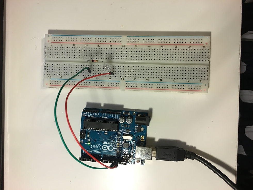
1/04 Connect LED with a solderless breadboard with 1K ohm resistor via Pin 11
As I need to shift an output from Pin 13 to Pin 11,
I edited pinMode and also digitalWrite from 13 to 11.
// the setup function runs once when you press reset or power the board
void setup() {
// initialize digital pin 13 as an output.
pinMode(11, OUTPUT);
}
// the loop function runs over and over again forever
void loop() {
digitalWrite(11, HIGH); // turn the LED on (HIGH is the voltage level)
delay(100); // wait for a second
digitalWrite(11, LOW); // turn the LED off by making the voltage LOW
delay(100); // wait for a second
}
- -
1/05 Add the second LED
2 lights blink alternately :
I added one more light on Pin 12,
then added another pinMode and also copied another set of void loop.
// the setup function runs once when you press reset or power the board
void setup() {
// initialize digital pin 13 as an output.
pinMode(11, OUTPUT);
pinMode(12, OUTPUT);
}
// the loop function runs over and over again forever
void loop() {
digitalWrite(11, HIGH); // turn the LED on (HIGH is the voltage level)
delay(100); // wait for a second
digitalWrite(11, LOW); // turn the LED off by making the voltage LOW
delay(100); // wait for a second
digitalWrite(12, HIGH); // turn the LED on (HIGH is the voltage level)
delay(100); // wait for a second
digitalWrite(12, LOW); // turn the LED off by making the voltage LOW
delay(100); // wait for a second
}
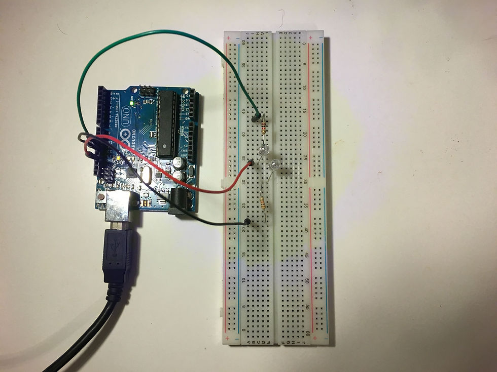
2 lights blink simultaneously :
I only connected the breadboardwith Pin 11, however, I need to add more set of LED and a resistor.
[Debug]
In this case, I have brought a wrong resistor for the second light, so the both lights blink with lower brightness.

- -
1/06 AnalogReadSerial
// the setup routine runs once when you press reset:
void setup() {
// initialize serial communication at 9600 bits per second:
Serial.begin(9600);
}
// the loop routine runs over and over again forever:
void loop() {
// read the input on analog pin 0:
int sensorValue = analogRead(A0);
// print out the value you read:
Serial.println(sensorValue);
delay(1); // delay in between reads for stability
}

- -
1/07 AnalogInput
*/
int sensorPin = A0; // select the input pin for the potentiometer
int ledPin = 11; // select the pin for the LED
//int ledPin = 11; // select the pin for the LED
int sensorValue = 0; // variable to store the value coming from the sensor
void setup() {
// declare the ledPin as an OUTPUT:
pinMode(ledPin, OUTPUT);
}
void loop() {
// read the value from the sensor:
sensorValue = analogRead(sensorPin);
// turn the ledPin on
digitalWrite(ledPin, HIGH);
// stop the program for <sensorValue> milliseconds:
delay(sensorValue);
// turn the ledPin off:
digitalWrite(ledPin, LOW);
// stop the program for for <sensorValue> milliseconds:
delay(sensorValue);
}


Comments